A crowbar circuit is usually placed across the power supply’s output terminals, to protect the load against any overvoltage. It does this by shorting the terminals (placing a crowbar across) which deactivates the protection device. It may blow up the fuse, trip the circuit breaker or shut down some parts of the circuit so as to cut off the power to the load. The protection is used for both low and high voltage power supplies.
The crowbar protection uses a sensing circuit to monitor the supply’s output voltage and compare it against a preset value. In the event of an overvoltage, it triggers the crowbar device which in turn short circuits the output terminals, hence cutting off the power.
The two commonly used components for the crowbar device are the silicon controlled rectifier (SCR) known as thyristor and the MOSFET. The monitoring circuit, and crowbar device, depends on the sensitivity of the circuit protected and the type of stresses expected or experienced. A successive protection will depend on whether the protected circuit or load can survive the excess voltage and the protection device’s response time.
The overvoltage or other fault conditions may arise due to operator error, a fault in either the load or the power supply. Due to the nature and sensitivity of the present day electronics and extremely low operational voltages, it is important to ensure that the safe voltages are not exceeded. Otherwise the excess voltages can damage expensive and sensitive equipment.
A simple circuit is shown below:
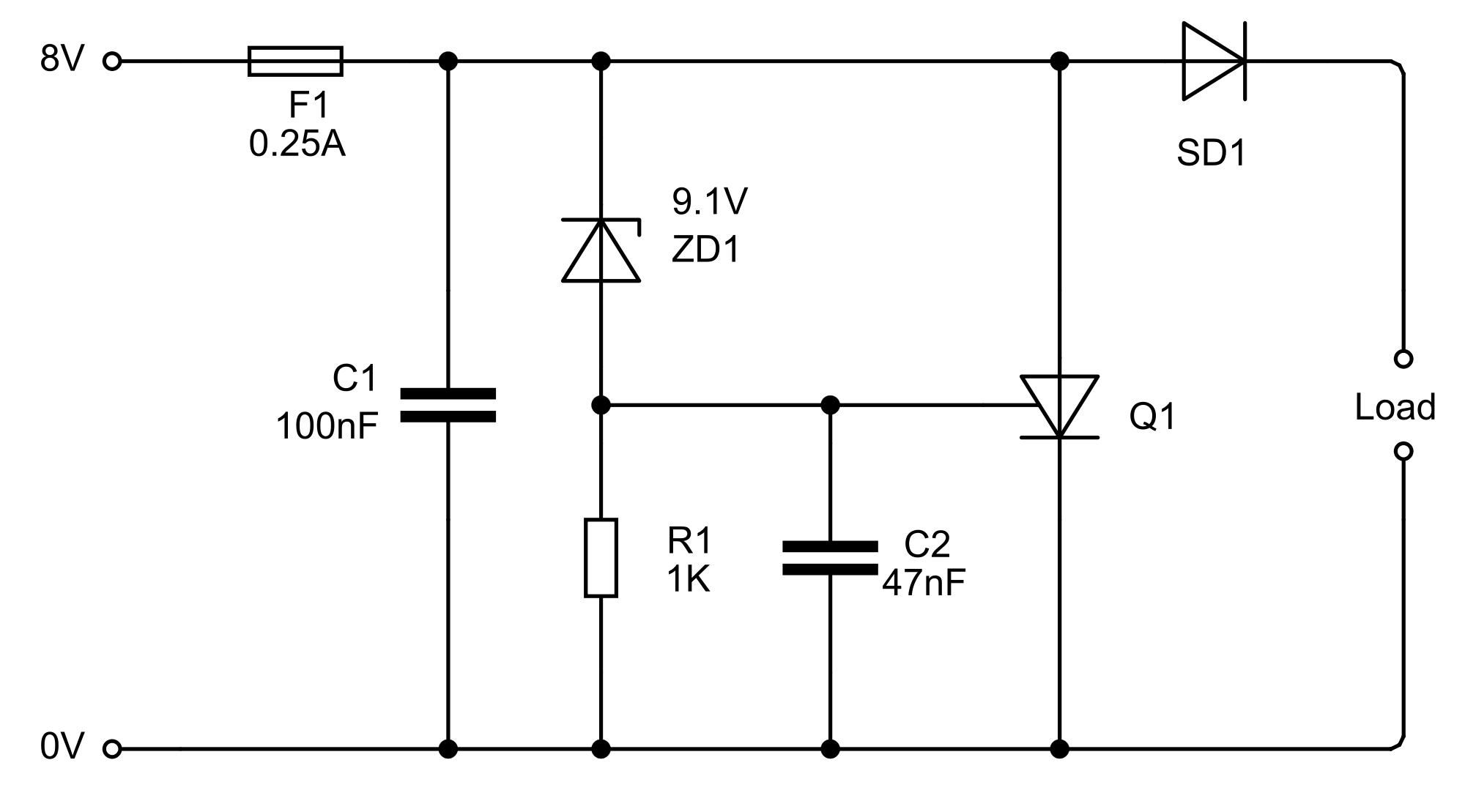
This circuit uses an 8V supply and has its overvoltage protection set at 9.1V; this can be adjusted by changing to the zener diode with the preferred voltage. At 9.1V, the zener diode ZD1 starts to conducts and cause a trigger signal to switch on the thyristor Q1.
The fuse F1 blows up once the current exceeds its rated 250mA. Capacitor C1 is used to take care of the small voltage spikes, noise and other harmless fluctuations which may erroneously trigger the circuit.
In an active crowbar the fuse is not designed to blow and the protection removes the short once transient is over, allowing the system to resume its normal operation. An active protection circuit does not use the thyristor for the short circuiting; instead they utilize a gate turn off thyristor (GTO), a transistor or a forced commutated thyristor, all of which can be switched off using an appropriate signal.
A crowbar protection is:
- Easy and cheap to construct
- Has a low holding voltage and hence lets high fault currents to flow without dissipating a lot of heat
- It draws attention to the equipment or fault condition when it deactivates the protective devices by tripping the circuit breaker or blowing the fuse
- Prevent serious damage to sensitive and expensive electronic equipment