What is a Forward Converter?
A forward converter is a switching power supply circuit that transfers the energy from the primary to the secondary while the switching element is “on,” which is the opposite of a flyback converter.
Forward and fly back converters are the two commonly used topologies used to either increase or decrease D.C voltages, or convert a single voltage to multiple D.C output voltages.
A typical forward converter consists of a:
- Transformer which is either a step-up or step-down with a single or multiple secondary windings. The type used depends on the available input voltage and desired output voltage. It also provides isolation of the load from the input voltage.
- Transistor such as a MOSFET which acts as the switching device
- Diodes
- Capacitors
- Inductor
Energy is passed directly through the transformer during the transistor’s conduction phase. The output voltage is determined by the input voltage, the transformer turns ratio and the duty cycle.
The two commonly used topologies are the single switch, and two switch forward converters.
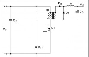
Single switch forward converter operations
When the transistor switch Q1 is ON, current flows in the primary winding and causes a secondary current to flow, through DR and the output filter. This gives an output voltage Vo. When the transistor is switched off, the transformer voltage will tend to reverse the action and increase the voltage at the cathode of Diode DTR until it turns on.
Advantages of single switch converter
- Simple construction and operation
- Low input capacitor ripple current
- Lower current on the secondary diodes
Disadvantages
- Requires a high transistor rating (twice the input voltage)
- Requirement for an active snubbers circuits for resetting the transformer core
- higher conduction losses
- Bigger transformer
Two switch forward converter operations
Energy is transferred from the primary to the secondary of the transformer when the two transistors are simultaneously turned on. When the transistors are off, the transformer magnetizing current flows back to the source, through diodes D1 and D2 which are now forward biased. The diodes conducts until all the magnetizing energy in the primary along with the energy stored in the leakage inductances is returned to the input supply.
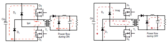
Fig. 1a) Power Transfer Stage of Operation Fig. 1b) Power Flow from Output Cap to Power Load – Image Source
To ensure a transformer reset during the OFF time, a duty cycle of less that 50% is used to give a longer OFF time than the ON time. In this operation, the primary winding of the transformer acts as the reset winding.
Benefits of two switch forward Converters
- Does not require a snubber circuit
- Less voltage stress for the MOSFET (same as input voltage)
- Simple construction and operation over a wide range of input and output voltages
- Ability to provide multiple isolated outputs
- Low system power losses and noise
Disadvantages
- Limited frequency of operation
- Slightly expensive since it uses more components
- larger components (transformer and inductor)
The single switch converter is used for power outputs of up to about 100W. The two switch converter is preferred for most applications due to its reliability and efficiency and widely used in the ATX power supply units with outputs of between 150 and 750 W.