There are two categories of frequency filters based on the circuit components and operation.
Passive Frequency Filters
Passive frequency filters use passive components such as the resistors, capacitors and inductors and do not increase or decrease the amplitude of the required frequency. The passive filters attenuate the unwanted frequencies and have an output level slightly lower than the input. The resistor-capacitor (RC) networks are used for low frequencies up to 100 KHz and the resistor-inductor-capacitor (RLC) networks for higher frequencies above 100 KHz
Active Frequency Filters
Active frequency filters use active amplifying components such as transistors and operational amplifiers (opamps), which are used to increase the signal strength and can have higher outputs that the input signal level. The active filter is not affected by variations in load resistance or reactance as with the passive filters. They provide better filtering performance at the cut off frequencies and the amplifier allows one to specify and easily adjust cut-off frequency, pass band gain and ripple
Types of filters
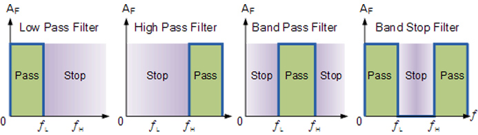
The five main types of frequency filters are the high pass, low-pass, all-pass, band pass, and notch filters. Their characteristics are determined by the type and values of circuit components used as well as their arrangement. The classification is based on the frequency range that a filter allows to passes through.
- Low pass filter allows low frequency signals ranging from 0 Hz to the designed cut-off frequency point and attenuates the higher frequencies.
- High pass filter allows those signals above the cut off frequency and blocks all the lower ones.
- Band pass filter allows signals within the specified band of frequencies to pass while blocking the higher and lower frequencies outside this band.
- Band stop attenuates signals within the specified band or range and allows both higher and lower frequencies outside the band to pass.
Typical RC Low Pass Filter Circuit
A simple passive filter contains a resistor and a capacitor, while the more complex filters combine several active and passive components. Since capacitive reactance is inversely proportional to frequency, it is much larger at low frequencies and causes more voltage to be dropped across the capacitor as compared to that across the resistor. At higher frequencies, the capacitive reactance is lower than the resistor’s value and voltage across the capacitor is less. The filter’s output is the voltage across the capacitor and hence will be lower at higher frequencies and high at low frequencies.
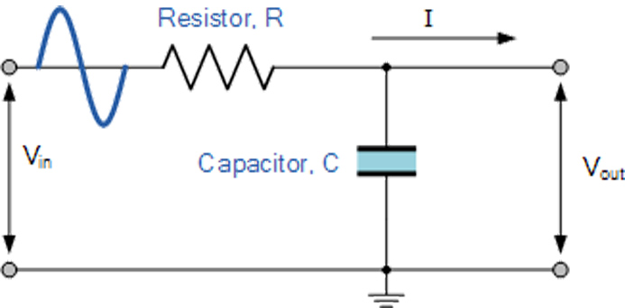
Image Source
Frequency filters are used in a variety of telecommunication and electronics such as power supplies, biomedical systems, space satellites and other sophisticated electronic systems.