What is a Power Converter?
A converter is an electrical circuit which accepts a DC input and generates a DC output of a different voltage, usually achieved by high frequency switching action employing inductive and capacitive filter elements.
A power converter is an electrical circuit that changes the electric energy from one form into the desired form optimized for the specific load. A converter may do one or more functions and give an output that differs from the input. It is used to increase or decrease the magnitude of the input voltage, invert polarity, or produce several output voltages of either the same polarity with the input, different polarity, or mixed polarities such as in the computer power supply unit.
The DC to DC converters are used in a wide range of applications including computer power supplies, board level power conversion and regulation, dc motor control circuits and much more.
The converter acts as the link or the transforming stage between the power source and the power supply output. There are several kings of converters based on the source input voltage and the output voltage and these falls into four categories namely the AC to DC converter known as the rectifier, the AC to AC clycloconverter or frequency changer, the DC to DC voltage or current converter, and the DC to AC inverter.
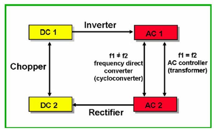
Fig 1 Power converter specifications
The converter uses non linear components such as the semiconductor switches, and linear reactive components such as the inductors, transformers and capacitors for intermediate energy storage as well as current and voltage filtering. The size, weight and cost of the converter are largely determined by these components.
There three basic converter circuits that are widely used in DC to DC converters are the buck, boost, and the buck and boost. These configurations are the most used topologies due to their simplicity and use of fewer components. Each has its advantages and drawbacks which determines the suitability for any specific application.
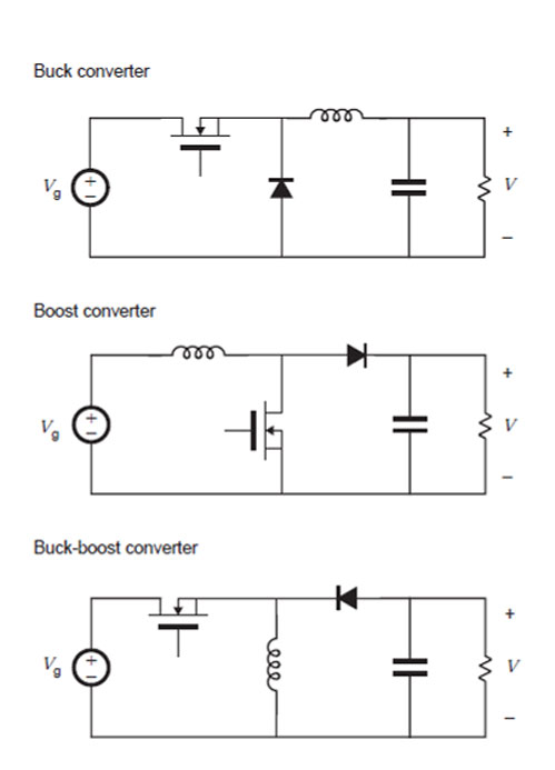
Figure 2 non-isolated converter circuit arrangements
The buck converter is a step-down, the boost a step-up while the buck-boost is both step-up and step-down. All these are non-isolated and use the inductor as the energy transfer element and are mostly used in board level power conversion and regulation.
The isolated dc to dc converters use a transformer to provide the isolation, multiple outputs, a different voltage level, or polarity depending on the turns ratios and directions of the windings.
They are based on the non-isolated topologies but with the inclusion of a transformer. The commonly used types are, the full bridge, the half bridge, forward and the push pull converters, which are the isolated versions of the buck; and the flyback which is the isolated version of the buck-boost converter.
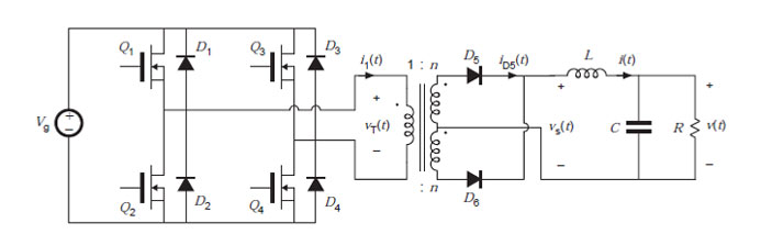
Figure 3 Full Bridge isolated buck converter
To improve performance, high frequencies and fast switching power semiconductor devices are used. The high frequencies increase the efficiency while reducing the physical sizes of the supplies since they allow the use of smaller components. The frequencies are usually above the audible range and in the range of between 20 KHz and 200 KHz. A feedback and duty cycle control circuit is usually used to adjust the turn-on and turn-off conditions to maintain a constant voltage at the output regardless of the load current or variations in the supply voltage.
Converters are widely used in the electronic equipment, in power supplies and other circuits requiring specific voltage and current levels other than the available raw supply energy. The converters provide any type of the required voltage at the desired magnitude. With a proper design and use of the almost ideal components, the available methods of conversion offer variety of reliable and efficient energy to power most of the electronic devices and components.