What is Inrush Current?
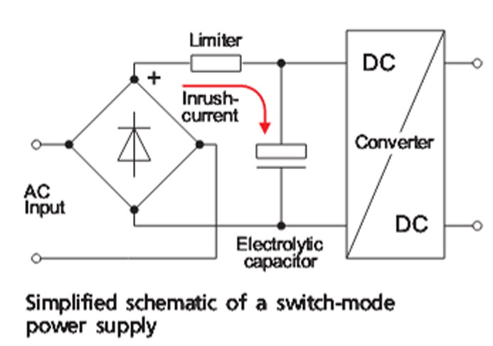
Inrush current is the instantaneous high input current drawn by a power supply or electrical equipment at turn-on. This arises due to the high initial currents required to charge the capacitors and inductors or transformers.
The inrush current is also known as the switch–on surge, or the input surge current.
At turn-on, the discharged capacitors in power supplies offer low impedance that allows high currents to flow into the circuit as they charge from zero to their maximum values. These currents can be as high as 20 times the steady state currents. Even though it only lasts for about 10ms it takes between 30 and 40 cycles for the current to stabilize to the normal operating value. If not limited, the high currents can damage the equipment in addition to producing voltage dips in the supply line and causing malfunctioning of other equipment powered from the same supply.
Inrush current specifications
High inrush currents indicate more stress on the rectifier components and hence lower reliability. The inrush current is specified in terms of:
- Average during a half cycle or peak: – where peak is about 40% larger than the average
- Voltage range – 120V or 240V
- Operating temperature range in which the limiting technique is effective
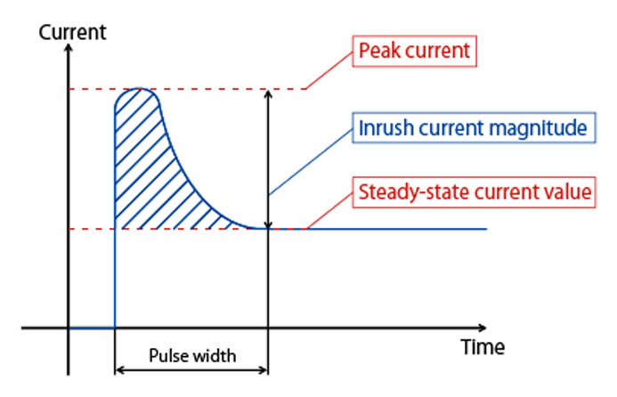
Current waveform when the device is powered up – Image Credit
Limiting inrush currents
The two commonly used protection methods are, the passive, where a resistive current limiting device is connected in series with the supply, and the active which uses an electronic circuit consisting of resistors, a switching device and a control circuit.
Resistor in Series
For small wattage supplies, the resistor is connected in series with the power input line. However, the method is not suitable in larger power supplies due to inefficiency caused by the high power dissipation and losses in the series resistor.
NTC thermistors
The method uses negative temperature coefficient (NTC) resistor connected in series with the power input line.
At ambient temperature the NTC device exhibits a high resistance, when the power is turned-on, the high resistance limits the amount of inrush current flowing into the circuit. As the current flows, the thermistor temperature increases thereby reducing the resistance significantly. This stabilizes at less than one ohm, and is able to allow the steady state current to flow into the circuit.
Parallel electronic switch
Using an electronic switch or relay in parallel with the thermistors or resistor. The currently limiting device offers high resistance at startup after which the switch is turned on to short circuit the device. The method ensures that thermistor is able to cool down to its initial resistance and be ready to protect against a subsequent surge in case of a power failure and resumption, or when one switches off an equipment and then turns it one immediately.
Active circuits
An active circuit comprises of resistors, transistors, triacs or thyristors and a control circuit to drive the switching device. These are suitable for applications requiring hot restart capabilities.
The choice of the protection method depends on frequency of inrush currents, cost, equipment power level, reliability expected and performance. The NTC thermistor is widely used as the limiting device and preferred for its simple design and low cost as compared to the active circuit, however, it has some drawbacks which make it unsuitable for use in extreme weather conditions or for sensitive applications.
Factors considered when designing for inrush current limiting.
- Load capacitance value
- Steady current
- Ambient temperature
- Supply voltage
- Required current reduction of the inrush current
Soft start function, low inrush current power supplies