Power Supplies FAQs
Constant voltage power supplies provide a stable regulated voltage; this means that the output voltage will remain constant regardless of the varying AC input. During operation the output voltage will be regulated to within voltage tolerance which normally stands at 1-2%.
Constant current on the other hand provides a stable output current whilst the voltage can vary. Sunpowers constant current LED power supply range possesses both constant voltage and constant current characteristics. Sunpowers Constant current drivers operate at start up in constant voltage mode. Once the output current rated load is exceeded and it reaches the constant current region the LED driver will operate in constant current mode. This type of operation allows for direct drive of LEDs and can allow a more flexible system design.
Several of Sunpowers power supplies have a fan control based on the internal temperature. This function is there to extended the lifetime of the power supply, the fan will operate once the internal temperature of the power supply is reached sending a start up signal.
We cannot 100% guarantee that the final system will meet EMC requirements, Sunpower power supply test results are based on the setup shown in the EMC reports. The installation environment, wiring location, grounding and other contributing factors can cause a power supply to operate differently therefore influencing its EMC characteristics. This system as a whole would then need to be tested by an EMC testing house.
When 2 Power Supplies are connected in parallel, they can share the load if the following steps are taken.
Step 1. Measure the output voltages at no load from Anode1 to Ground i.e. Voltage Anode1 to Ground of PSU1 and Voltage Anode2 to Ground of PSU2. If the voltages are not the same, follow Step 2. If they are the same, skip to Step 3.
Step 2. Adjust the output voltages, with the help of VR on the Power Supply front panel market as ADJUST, to the same level. For e.g. if PSU1 is measuring 24.15Vdc and PSU2 is measuring 24.25Vdc, adjust the output voltage of one to be the same as the other.
Step 3. Connect the Power Supply to the end system load and measure the output voltages from A1 to Ground i.e. Voltage Anode 1 to Ground of PSU1 and Voltage Anode 2 to Ground of PSU2. Ensure that the output voltages are the same even after the 2 Power Supplies are connected to load. If not, adjust them with the VR available on the front panel. A tolerance of +/-25mV would be acceptable.
Please Note
1) If the output voltage of any Power Supply is higher, it will take the initial load and share the maximum load.
2) If the output voltages are the same, then an approximately equal load current sharing between the 2 Power Supplies can be achieved.
3) The ORing diode must be of an appropriate rating. The rating must be at least 4 times of the output load current and at least reverse voltage rating of 20Vrr.
4) The use of a heat sink is advised to ensure the ORing Diode does not overheat.
5) Recommended product for parallel operation up to 20A: DR-RDN20
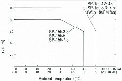
Applications of power supplies are diverse in the mechanical limitations, some of which may require the power supply to be in a vertical position. To ensure the power supply will function correctly when installed in a vertical position the derating curve is vital due to the heat concern. If the power supply has a built in fan or a forced cooling system, vertical or horiontal installation will have no difference on its operation.
The image below shows the SP-150's derating curve, the ambient temperature between horizontal and vertical is 5°C difference. If forced air cooling by a fan the ambient temperature can increase up to 20%
This page is to illustrate how to create a dual output when using two single output units, connected in series for positive and negative outputs.
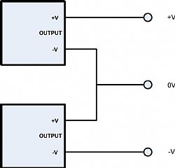
NOTE: Individual models must have:
1) Input isolated from output
2) Output isolated from earth