Power Supply Safety Standards
All good design and manufacturing processes will consider the regulations put into place and other power supply safety standards to ensure their products are suitable for use in their intended applications and minimise any impact they may have on the surrounding environment.
We understand that the responsibilities of the power supply designer extend beyond the mere functionality of a unit and need to focus on the requirements of power supply safety standards that apply within their field, we will therefore detail below some of the safety standards that our power supplies can be designed to comply with.
CE Marking of LED Drivers, as an essential component either internally or externally, can determine whether your LED luminaire will have the ability to meet the requirements of CE Marking. As an LED luminaire is an item of low-voltage electrical equipment, it requires CE compliance and marking if intended for sale within the EU. This shows that it meets EU safety, health and environmental standards. Because LED luminaires depend critically on LED drivers to generate the DC power they need, the drivers’ CE compliance has a major influence on that of the luminaires. Designers and manufacturers must accordingly take great care in selecting suitably certified and documented drivers to ensure trouble-free certification of their own products.
In this article, we look at the aspects of CE compliance that apply to LED luminaires and then explain their implications for driver choices.
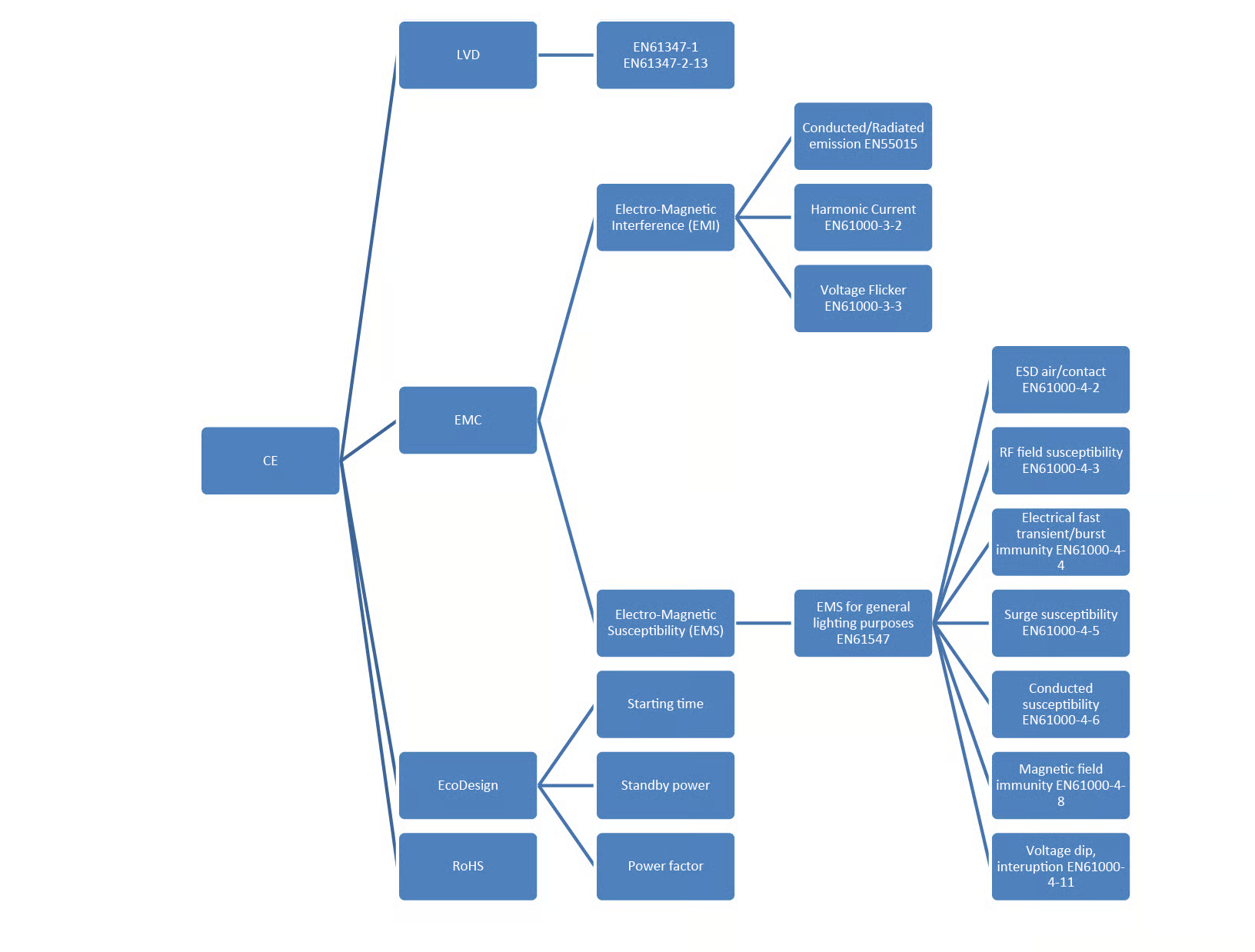
CE marking, as applicable to LED luminaires, comprises several requirements, including LVD safety, RoHS, electromagnetic compatibility (EMC) and Ecodesign. Many users are aware of the first three, as they have been part of CE compliance for many years. Ecodesign is a more recent requirement, but it has become mandatory for all products placed on the market, irrespective of where they are installed. Products falling within the scope of Ecodesign must bear the CE mark, and the manufacturer must mention a reference to the framework directive 2009/125/EC in the CE declaration.
Fig.1 shows the CE marking composition applicable to LED drivers and control gear. It illustrates LVD safety and the other major requirements, together with their hierarchical connection to the standards that define them.
Medically approved power supplies are obligatory to medical device manufacturers to ensure the safety of patients in both hospital and non-hospital environments. The MOPP (Means of Patient Protection) and MOOP (Means of Operator Protection) EN60601-1 approval was designed to ensure that those manufacturers selecting a power supply for a medical device have standards to abide by.
The MOPP (Means of Patient Protection) was designed for medical equipment where patient contact is required, where as MOOP (Means of Operator Protection) was designed for medical equipment where patient contact is not required. An example of such medical equipment can be found below:
MOPP (Means of Patient Protection) – Dialysis machine, Electro surgery unit, ventricular assistance devices & electrocardiography.
MOOP (Means of Operator Protection) – Air flow measurement equipment, nurse call system & patient information centre screens.
EN60601-1 Symbol for type B, not conductive applied part and usually earthed

EN60601-1 Symbol for type B, not conductive applied part and usually earthed
EN60601-1 Symbol for type BF, (Body Floating) conductive applied part and not earthed with 1 MOPP

EN60601-1 Symbol for type C, (Cardiac Floating) same as type BF but more stringent in leakage current and suitable for cardiac usage.

ISO 7637-1:2002
Road vehicles - Electrical disturbances from conduction and coupling - Part 1: Definitions and general considerationsAbstract
This part of ISO 7637 defines the basic terms relating to electrical disturbances from conduction and coupling used in its other parts, and gives general information on the whole of ISO 7637 and common to all parts.Normative References: IEC 60050-151, IEC 60050-161
ISO 7637-2:2004
Road vehicles - Electrical disturbances from conduction and coupling - Part 2: Electrical transient conduction along supply lines onlyAbstract
ISO 7637-2:2004 specifies bench tests for testing the compatibility to conducted electrical transients of equipment installed on passenger cars and light commercial vehicles fitted with a 12 V electrical system or commercial vehicles fitted with a 24 V electrical system -- for both injection and the measurement of transients. Failure mode severity classification for immunity to transients is also given. It is applicable to these types of road vehicle, independent of the propulsion system (e.g. spark ignition or diesel engine, or electric motor).Normative References: ISO 7637-1 : 2002, ISO 8854 : 1988.
The electromagnetic compatibility directive (2004/108/EC) was created to regulate the compatibility of equipment regarding EMC, to guarantee the free movement of apparatus and to create an acceptable electromagnetic environment in the community territory.
The directive (2004/108/EC) aims to remove barriers to trade within the European Economic Area whilst ensuring that the electromagnetic disturbance generated by apparatus does not exceed a level allowing radio and telecommunications equipment and other apparatus to operate as intended, and that apparatus has an adequate level of intrinsic immunity to electromagnetic disturbance to enable it to operate as intended.
The requirements apply to:
- Apparatus - A Finished appliance or combination of appliances made commercially available as a single functional unit
- Fixed installations - A particular combination of several types of apparatus and other devices, which are assembled, installed and intended to be used permanently at a pre-defined location
However, separate provisions should be made for each. This is so because whereas apparatus as such may move freely within the community, fixed installations, on the other hand, are installed for permanent use at a predefined location as assemblies of various types of apparatus and, where appropriate, other devices. The composition and function of such installations correspond, in most cases, to the particular needs of their operators.
The requirements do not cover the following areas
- Radio equipment and telecommunications terminal equipment due to being covered by directive (1999/5/EC).
- Aeronautical products, parts and appliances.
- Equipment which is inherently benign in terms of electromagnetic compatibility.
- Equipment that is incapable of generating or contributing to electromagnetic emissions which exceed a level allowing radio and telecommunication equipment to operate as intended.
- Equipment that will operate with unacceptable degradation in the presence of the electromagnetic disturbance normally consequent upon its intended use.
Electromagnetic disturbance is any electromagnetic phenomenon which may degrade the performance of equipment.
The current Electromagnetic Compatibility - EMC Directive 2004/108/EC applies to a vast range of equipment encompassing electrical and electronic appliances, systems and installations.
The main objective of the Directive is to guarantee the free movement of apparatus and to create an acceptable electromagnetic environment in the Community. In order to achieve it, a harmonised and acceptable level of protection is requested in the Directive, based on Article 95 of the Union Treaty, leading to full harmonisation in the Community.
The level of protection requested is further specified in the EMC Directive by protection aims in the field of electromagnetic compatibility. The main goals are:
To ensure that the electromagnetic disturbances produced by Equipment does not affect the correct functioning of other apparatus as well as radio and telecommunications networks, related equipment and electricity distribution networks.To ensure that equipment has an adequate level of intrinsic immunity to electromagnetic disturbances to enable them to operate as intended
From 20 April 2016, 2004/108/EC will be replaced by 2014/30/EU. The new Directive explicitly specifies the function and responsibility of each party who places electrical equipment onto the market.
Electromagnetic Compatibility - EMC Directive 2004/108/EC and LED Drivers
EMC Directive 2004/108/EC coverage of LED drivers includes a list of harmonised standards for LED lighting equipment as shown in Table 1 below. The EMC and interference standards may differ from those for households and industry. Accordingly, care must be taken in choosing standards appropriate to the requirements of LED lamps.
EMI emission EN55015 and harmonic current EN61000-3-2 are the most essential standards for LED drivers. If an LED driver meets both these standards, the next step is to check if it complies with Voltage Flicker EN61000-3-3 and EMS EN61547, which covers other test items.
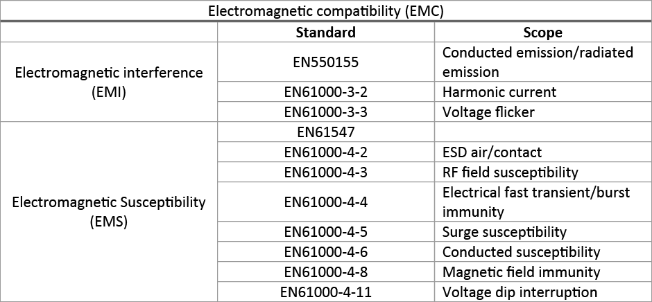
Table 1: A list of harmonised standards for lighting equipment within EMC Directive 2004/108/EC
Notes on harmonic current: EN61000-3-2 describes the permissible harmonic current emissions for devices with an input current of up to 16 A per phase. LED drivers rated below 25 W have no limit values for harmonics. LED drivers with an effective input power above 25 W must comply with the limits shown in Table 2.
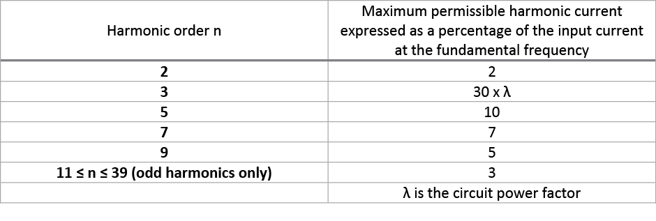
Table 2: Harmonic current limits for LED drivers > 25 W
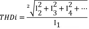
The relationship between harmonic current and power factor is shown in the equation below. Although the harmonic currents of LED drivers rated below 25W are not regulated here, they are regulated in the Ecodesign Directive by reference to the power factor:
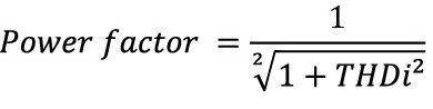
Where THDi is total harmonic distortion, I1 is fundamental current, I2 is second-order harmonic current etc.
Ecodesign regulations are intended to promote environmentally friendly design, reducing the environmental impact of Energy Related Products (ErP) throughout their entire product lifespan.
The regulations require manufacturers to decrease the energy consumption of their products by establishing minimum energy efficiency standards. By setting these standards at the European level, manufacturers do not have to navigate through multiple national regulations when launching their products on the market.
The ecodesign requirements for individual product groups are created under the EU's Ecodesign Directive, a process managed by the European Commission. As an alternative, industry sectors may also sign voluntary agreements to reduce the energy consumption of their products.
The energy related products directive 2009/125/EC aims to reduce energy consumption and other negative environmental impacts of products throughout the life-cycle by through eco-design (integration of environmental aspects at a very early stage in product design).
Phased introduction
The ecodesign requirements have been/are being introduced in three stages. Stage 1 appeared in September 2013, Stage 2 in September 2014, and Stage 3 is due in September 2016. Earlier requirements continue to apply alongside the later introductions.
Energy related products directive 2009/125/EC for LED Drivers
The energy related products directive 2009/125/EC requirements apply to:
- Energy-using products
- Products which do not consume energy but which impact on energy consumption, for example windows and installation materials
The requirements do not cover the following areas:
- Transport for persons or goods
- Voltage converters
- Uninterruptible power supplies
- Battery chargers
- Halogen lighting converters
- External power supplies for medical devices
For more information on European Ecodesign legislation applicable to LED lighting, see Commission Regulation (EC) No 1194/2012 of 12 December 2012 implementing Directive 2009/125/EC of the European Parliament and of the Council with regard to ecodesign requirements for directional lamps, light emitting diode lamps and related equipment.
Functionality requirements for LED lamps include Survival Factor, number of switching cycles before failure, starting and warm-up time, premature failure rates, colour rendering and consistency, and for lamps with integrated control gear, the lamp power factor (PF).
From Stage 2, equipment designed for installation between the mains and the LEDs – including the LED drivers – must comply with state of the art requirements for compatibility with lamps whose energy efficiency index reaches certain specified values. If this compatibility does not exist, warnings to this effect must be published on publicly available free-access websites and in other forms the manufacturer deems appropriate.
When a dimming control device is switched on at its lowest control setting for which the operated lamps consume power, the operated lamps shall emit at least 1 % of their luminous flux at full load.
There are three ecodesign issues which form part of energy related products directive 2009/125/EC for LED drivers and control gear, that are particularly important: Starting time, standby power and power factor. Further information on these is given below.
2009/125/EC for LED Drivers - Starting time
The starting time requirement of non-directional and directional LED lamps is less than 0.5 seconds. To comply with this, the average starting time of lamps in a test batch is no higher than the required starting time plus 10%, and no lamp in the test batch has a starting time more than two times the required value.
2009/125/EC for LED Drivers - Standby power consumption
Standby power refers to the lowest average power consumption of an LED driver or other item of control gear when the mains voltage is applied but the connected lamp(s) are not emitting light. The limits are shown in Table 3. Note that they will become more severe after September 2016.
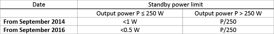
Table 3: Standby power limits imposed by ecodesign
These standby power requirements apply to controllable and dimmable electronics. If the control gear has additional functions such as sensor or network connections, their power consumption shall not be included in the above limits. Fig. 2 shows the logic of this.
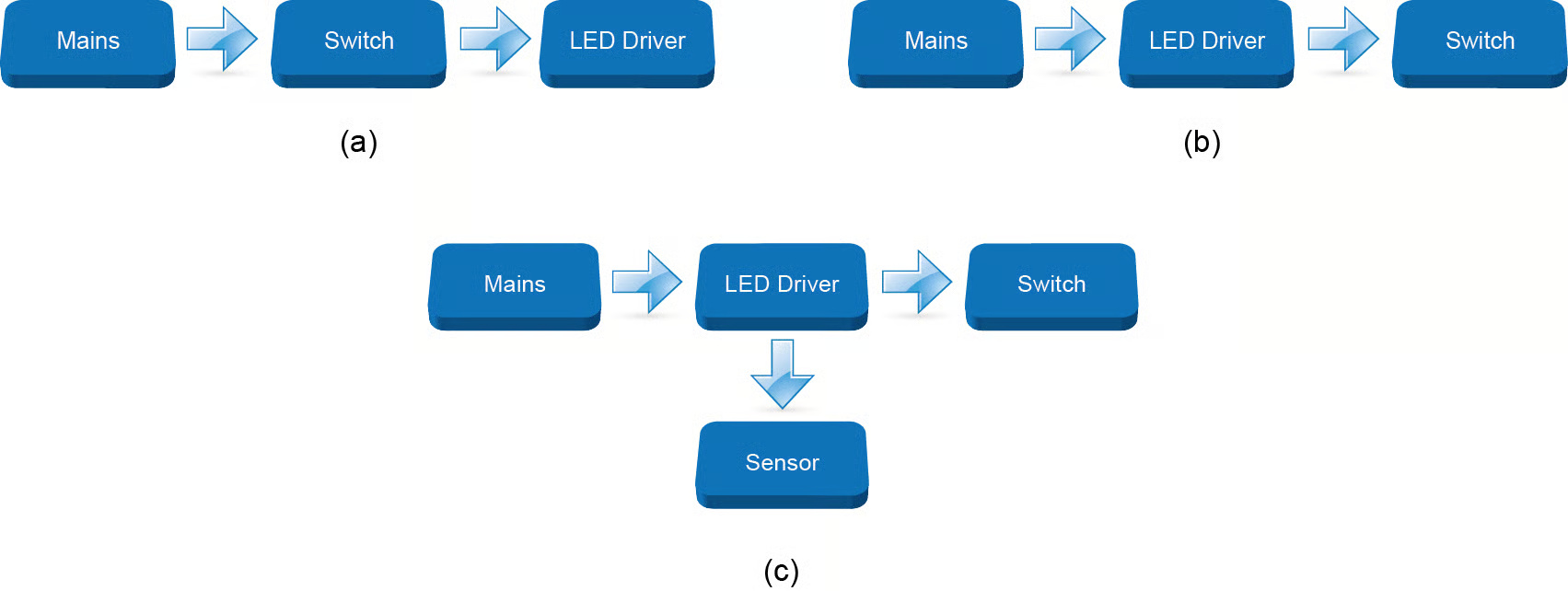
Fig 2: LED Driver configuration & standby requirements
Fig. 2:
(a) Switch before LED driver: No need to meet standby power requirement
(b) Switch after LED driver: Must meet standby power requirement
(c) Sensor or network connection: No need to meet standby power requirement
Note that the 2009/125/EC Directive also defines a no-load power requirement. This applies only where the LED lamp on/off switch is in the output circuit of the control gear.
2009/125/EC for LED Drivers - Power factor
The power factor requirement of non-directional and directional LED lamps with integrated control gear is shown in Table 4.
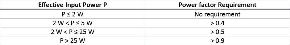
Table 4: LED lamp power factor requirement
Note that the Ecodesign directive regulates harmonic current limits for LED drivers rated below 25 W, even though EMC Directive EN61000-3-2 does not.
UL 1310 covers Class 2 power supplies and battery chargers intended for use in indoor and outdoor environments on alternating branch circuits with a maximum potential of 150V to ground. There are many areas to the scope as detailed below.
The requirements apply to
- Portable and semi permanent mounted direct plug-in units provided with 15A blade configurations for use on nominal 120 or 240V branch circuits
- Cord and plug connected units provided with a 15 or 20A attachment plug configuration and Units permanently connected to the input supply.
- Within the requirement units may also be provided with a direct current input jack for being powered from a vehicle battery adapter. These units utilise an isolated transformer and may incorporate components to provide an alternating or direct current output. Each output provides Class 2 power levels in accordance with the National Electrical Code, ANSI/NFPA 70. Maximum output voltage may not exceed 42.4V peak for alternating current, 60V for continuous direct current. These products are intended primarily to provide power to low voltage, electrically operated devices.
- Products whose input power does not exceed 660W under any possible condition of output loading.
- Class 2 products intended for use with toys. Products of this type shall also comply with the Standard of Toy Transformers, UL 697.
A product marked for a specific end-use may also be subjected to additional requirements found in the applicable end product standard.
Sunpower Class 2 Power Units include the newly released 100W Single Output IP67 Rated LED Lighting Power Supply.
The requirements do not cover the following areas
- The effect that a power unit may have on the equipment or system to which it is connected.
- Products intended to charge batteries for starter motors used to start engines. These are covered by the Standard for Battery Chargers for Charging Engine-Starter Batteries, UL 1236.
- Products with outputs other than Class 2, nor battery chargers intended to charge batteries employed in wheel chairs or similar types of mobility aids. Products of this type are covered by the Standard for Power Units Other Tan Class 2, UL 1012.
- Products without a rectifier, these may be covered by the Standard for Class 2 and Class 3 Transformers, UL 1585.
- Products solely powered by a dc source. These are covered by the Standard for Power Converters/Inverters and Power Converter/Inverter Systems for Land Vehicles and Marine Craft, UL 458 or by requirements appropriate to the intended application.
- Products intended for supplying low voltage landscape lighting. Products of this type are covered by the Standard for Low Voltage Landscape Lighting Systems, UL 1838.
The Low Voltage Directive (2006/95/EC), often shortened to LVD, is concerned with ensuring a high level of protection of public interests, such as health and safety of persons, domestic animals and property, and guaranteeing fair competition in the Union market. The Directive aims to harmonise the laws of the Member States relating to electrical equipment designed for use within certain voltage limits. It applies to equipment which is new to the Union market when it is placed on the market. This means it is either new equipment made by a manufacturer established in the Union, or electrical equipment, whether new or second-hand, imported from a third country.
The voltage limits, which apply to voltages at the equipment’s input or output terminals, are between 50 and 1000 volts for alternating current, and between 75 and 1500 volts for direct current. They do not cover voltages within equipment and do not apply to components.
Certain classes of equipment, covered by other technical standards, are listed in Annex III of the Directive as excluded from its scope. These items include medical devices, electricity meters, railway or maritime equipment, and electrical plugs and sockets for domestic use.
The current Low Voltage Directive is based on 2006/95/EC, but this will be replaced by 2014/35/EU from April 20, 2016. The new directive explicitly specifies the function and responsibilities of each party in the supply chain bringing the electrical equipment to market.
Low Voltage Directive (2006/95/EC) and LED Drivers
The LED driver used in a luminaire should fulfil both EN61347-1 as a general requirement and EN61347-2-13 for LED control gear safety approval. The current version of the general requirement is EN61347-1:2008+A1:2011. This is a technical revision of EN61347-1:2008 that brings in provisions for protective earthing, moisture resistance and insulation, and fault conditions, together with numerous other changes. It will remain valid until January 1, 2016. After this, EN61347-1:2008+A1:2011+A2:2013 will be applied to all existing and new products. The current LED control gear safety standard EN61347-2-13:2006 will remain valid until 8 October 2017. Accordingly, it is advisable to ensure that any chosen LED driver is certified to EN61347-1:2008+A1:2011+A2:2013 and EN61347-2-13:2006.
Electromagnetic compatibility (EMC Directive) governs the electromagnetic emissions of equipment in order to ensure that it does not disturb radio, telecommunications and other equipment. The directive also governs the immunity or susceptibility of the equipment to interference from radio emissions normally present, when used as intended.
There are various standards set out under this directive to standardise product safety and performance by the intended application. The base of the EMC Directive is 89/336/EEC, this has been modified by Directive 92/31/EEC, 93/68/EEC & 91/263/EEC. Repealed Directives include 76/889/EEC and 76/890/EEC. EMC Directive 89/336/EEC will be repealed by the new 2004/108 EC Directive in July 2007.
Product Standard & Description
CISPR 11:2003 - Limits and methods of measurement of radio disturbance characteristics of industrial, scientific and medical (ISM) radio-frequency equipment
CISPR 12:2001 - Limits and methods of measurement of radio disturbance characteristics of vehicles, motor boats and spark-ignited engine-driven devices
CISPR 13:2001 - Limits and methods of measurement of radio disturbance characteristics of sound and television broadcast receivers and associated equipment
CISPR 14-1:2000 - Limits and methods of measurement of radio disturbance characteristics of electrical motor-operated and thermal appliances for household and similar purposes, electric tools and similar electric apparatus
CISPR 14-2:1997 - Requirements for household appliances, tools and similar apparatus. Part 2: Immunity
CISPR 15:2000 - Limits and methods of measurement of radio disturbance characteristics of electrical lighting and similar equipment
CISPR 20:2002 - Limits and methods of measurement of immunity characteristics of sound and television broadcast receivers and associated equipment
CISPR 22:2003 - Limits and methods of measurement of radio disturbance characteristics of ITE
CISPR 24:1997 - Limits and methods of measurement of the immunity characteristics of ITE
CISPR 25:2002 - Limits and methods of measurement of radio disturbance characteristics for the protection of receivers used on board vehicles
You must ensure that you select the appropriate power supply based on the EMC standard that it is designed to as different equipment require varying degrees of electromagnetic emission and immunity protection.
Power Supply Environmental Standards
At Sunpower Electronics we help our customers use resources more efficiently by employing a host of power supply environmental standards, including:
- Higher efficiency designs using advanced technology to ensure a continual reduction in component count
- More efficient design topology that reduces energy consumption
- Reduction in failure rate, often even 0%, ensuring reliable trouble free operation
- Longer lifetime on product through cutting edge design leading to distant obsolescence
- Closed loop recycling systems for all raw materials
- Environmental energy saving programs
Above all we continue to invest heavily in power supply environmental standards and environmental research and development as we strive to improve the efficiency of our products and processes in all business areas.
Sunpower Electronics signed up to the 80Plus™ program to integrate more energy efficient power supplies into our range of available off the shelf products, custom units can also be designed to this standard upon request.
The 80 Plus™ performance specification requires power supplies to be 80% energy efficient or greater at 20%, 50% and 100% rated load with a power factor of 0.9 or greater. The test is very demanding, particularly achieving 80% efficiency at only 20% load.
A 80 Plus™ certified power supply not only saves energy costs they also increase the reliability of your system through reduced heat output and therefore decreases maintenance costs, lengthens equipment life and generally improves the comfort of your working environment (reduced heat output calls for minimised need for noisy PC fans, making a quieter office environment).
A selection of our 80Plus certified products can be found below or enter 80Plus in the search area to bring up all of our verified products.
Sunpower Electronics signed up to the Energy Star program to integrate more energy efficient power supplies into our range of available off the shelf products.
Energy Star is a voluntary labelling program designed to identify and promote energy-efficient products to reduce greenhouse gas emissions. The requirements differ with each application although the energy star program provides a trustworthy label on over 60 product categories. To qualify for energy star certification, products must pass a variety of tests to prove they are energy efficient, cost saving, high quality and meet specific lifetime criteria.
Ingress Protection Rating (IP Rating) indicates the level of protection to which a product is protected against the intrusion of solid objects or dust, accidental contact and water.
The RoHs and REACH Directive
The RoHs and REACH directive aims to restrict certain dangerous substances commonly used in electronic and electronic equipment. This (RoHS) European directive aims to control the use of certain hazardous substances in the production of new electrical and electronic equipment, it is a partner directive to the WEEE directive (Waste in Electrical and Electronic Equipment).
Any RoHs compliant component is tested for the presence of Lead (Pb), Cadmium (Cd), Mercury (Hg), Hexavalent chromium (Hex-Cr), Polybrominated biphenyls (PBB) and Polybrominated diphenyl ethers (PBDE).
Reach is the regulation for registration, evaluation, authorisation and restriction of chemicals. This directive applies to all chemicals not only chemicals used in industrial processes, for example those products used in our day-to-day life.
The RoHS regulations place the following requirements upon producers:
- Products placed on the market must not contain over the maximum concentration values of hazardous substances
- Documentation must be available for compliant products before placing them on the market
- Documentation must be maintained for 4 years after the product is retracted from the market
Ingress Protection Rating (IP Rating) indicates the level of protection to which a product is protected against the intrusion of solid objects or dust, accidental contact and water.
It is identified by a code of the letters IP followed by two digits and an optional letter. Where there is no protection rating with regards to one of the criteria the digit is replaced with the letter X.
Solid Particle Protection
The first digit indicates the level of protection that the enclosure provides against access to hazardous parts and the ingress of solid foreign objects.
0 - No protection
1 - Protected from large foreign objects >50mm
2 - Protected from medium sized foreign objects >12.5mm
3 - Protected from small foreign objects >2.5mm
4 - Protected from granular foreign bodies >1mm
5 - Limited ingress of dust, not in sufficient quantity to interfere with operation
6 - Totally protected from dust
Water Ingress Protection
The second digit indicates the level of protection that the enclosure provides against harmful ingress of water.
0 - No protection
1 - Protected against vertically dripping water
2 - Protected against vertically dripping water when the enclosure is at a angle of up to 15°
3 - Protected against water falling as a spray at any angle up to 60° from the vertical
4 - Protected from water splashing against the enclosure from any direction
5 - Protected from water projected from a nozzle against the enclosure from any direction
6 - Protected from strong jets of water from all directions
6K - Protected from strong jets of water with increased pressure from all directions
7 - Protected against ingress of water when enclosure immersed in water, in defined conditions or pressure and time, down to 1 meter
8 - Protected from continuous submission in water beyond 1 meter under conditions specified by the manufacturer
9K - Protected from powerful high temperature water jets
Additional Letters
The optional letter can be appended to classify only the level of protection against access to hazardous parts by persons:
A - Back of Hand
B - Finger
C - Tool
D - Wire
These other letters are be used to provide additional information:
F - Oil resistant
H - High voltage
M - Device moving during water test
S - Device standing still during water test
W - Weather conditions