What is Equivalent Series Resistance?
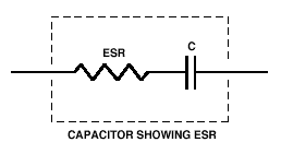
The equivalent series resistance of a capacitor is the internal resistance that appears in series with the capacitance of the device. Almost all capacitors exhibit this property at varying degrees depending on the construction, dielectric materials, quality, and reliability of the capacitor. The equivalent series resistance (ESR) values range from a few milliohms to several ohms, and results into power losses, reduced efficiency, and instability of power supplies and regulators circuits.
The aluminum electrolytic capacitors and tantalum ones, have higher ESRs than ceramic capacitors of the same capacitance and voltage rating. The polypropylene and polyester capacitors fall in between, but are not commonly used in the SMPSs due to their large physical sizes.
Main parts of an ESR
- Metallic resistance
- Electrolytic and paper resistance which is dependent on frequency and temperature
- Dielectric which depends on frequency
Factors that increase the ESR value
- Bad electrical connections; – The connection between the copper leads and the aluminum plates in the capacitor are usually welded or made using mechanical crimps. This type of connections introduces some series resistance, and is used because the aluminum cannot be soldered.
- The drying of capacitor electrolyte solution. As the liquid component of the electrolyte dries out due to elevated temperatures, the electrical resistance increases.
- ESR increases with increase in temperature and frequency. In power supplies with high currents, the power dissipation associated with the ESR may further increase the temperature and lead to capacitor failure.
Effect of frequency on ESR
The ERS is the portion of the capacitor’s impedance that causes the overall, real power losses. This is frequency dependant as can be seen from the equation below:
Where DFR, is the dissipation factor associated with contact resistance, DFL with leakage losses, and DFD the dielectric losses.
From above, the leakage and dielectric losses decrease with increase in frequency until the contact resistance dominates up to a specific point. Beyond this point, the ESR becomes very high at higher frequencies largely due to the skin effect of the ac signal.
Minimizing ESR in circuits
- High performance applications use the low ESR capacitors such as the low ESR solid polymer capacitors, tantalum capacitors and the multilayer ceramic capacitors (MLCC).
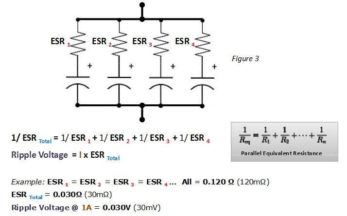
- Capacitors are connected in parallel in places such as the power supply smoothing circuits. Small value capacitors are connected in parallel as opposed to connecting a single large capacitor. This reduces the effective ESR in addition to reducing the ripple volatge, and allows the circuit to handle higher currents with less losses.
Parallel capacitor connection
Capacitor manufactures provide plots of the ESR over a specific frequency range, and one can easily determine the ESR at the intended frequency. Sometimes they do not specify the ESR and instead provides the dissipation factor. In such a case, the ESR is calculated from:
Where, DF is the total dissipation factor from all the loss elements of the capacitor.
Measuring Equivalent Series Resistance
ESR meters are used to measure the series resistance either in-circuit or out-of circuit. During the measurement, some of the meters will first performs a controlled discharge on charged capacitors before measuring the ESR and capacitance.
ERS is usually expressed as the maximum value at 120Hz and 100 KHz for the tantalum and aluminum electrolytic capacitors, and at 100 KHz for the film capacitors.
Advantages of low ESR capacitors
Low ESR capacitors have the advantage of minimizing capacitor losses, increasing the efficiency and stability of the power supply while reducing the output ripple voltage. Some ratings that result into lower ESR include a larger capacitance, low dissipation factor and low capacitor voltage.

